Fire alarm and emergency communication systems rely on correctly selected cabling to connect detection devices, alarm notification circuits, voice evacuation equipment and ancillary life-safety interfaces. Cable selection should be based on circuit function, electrical calculations, route conditions, electromagnetic interference and verified fire-performance evidence.
This guide provides consultants, contractors and system integrators with a practical framework for selecting between Heizka shielded and unshielded LSZH fire-resistant cable options. It does not prescribe one universal cable size or treat LSZH, flame propagation and circuit integrity as interchangeable properties.
Request a Fire Alarm Cabling Recommendation
Send the circuit function, system voltage, connected load, route length, shielding requirement, installation environment and applicable project specification for technical review.
Send your fire alarm cabling requirements to the Heizka technical team
1. Solution Overview
A reliable fire alarm cabling solution starts with the approved system design, not with a product name alone. Detection loops, notification circuits, voice evacuation systems and ancillary interfaces can have different electrical, environmental and fire-performance requirements. Each cable should therefore be reviewed against the equipment manufacturer’s instructions, the project specification, circuit calculations, installation route and supporting test evidence.
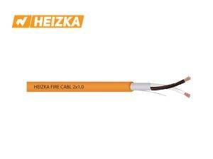
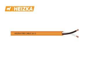
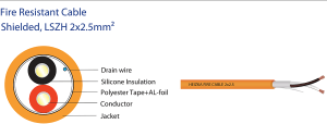
Heizka’s current fire-resistant cable family includes shielded and unshielded, two-core LSZH variants in 1.0 mm², 1.5 mm² and 2.5 mm² conductor sizes. The family allows designers to select shielding and conductor size separately, subject to the system requirements and project approval.
Recommended Cable Characteristics by Circuit
| Circuit or system area | Main design questions | Cable characteristics to evaluate |
|---|---|---|
| Detection and signaling circuits | What does the system manufacturer require? Is the route exposed to significant EMI? | Shielded or unshielded construction, conductor size, route suitability and project fire-performance requirement. |
| Notification circuits | What is the connected load and allowable voltage drop? | Conductor cross-sectional area, route length, installation method and circuit-survivability requirement. |
| Voice evacuation and emergency communication | What signal type, load and continuity requirement applies? | Signal integrity, shielding where required, voltage drop and equipment compatibility. |
| Ancillary life-safety interfaces | What systems are connected and how are the circuits supervised? | Interface type, segregation, shielding, conductor count and approved cause-and-effect design. |
| Emergency and critical loads | Must the circuit remain functional during a defined fire scenario? | SKU-specific test evidence, approved installation method and consultant acceptance. |
Engineering note: this table is a selection framework, not a substitute for circuit calculations, equipment instructions or approved project drawings.
2. Why Cabling Matters in Life-Safety Systems
The term “fire cable” can conceal several different engineering considerations. Circuit integrity, flame propagation, smoke density, combustion-gas properties and signal reliability address different risks. A project team should identify the exact requirement before comparing products, catalogues or certificates.
Circuit Integrity During Fire
Circuit integrity describes whether a cable circuit continues to operate under the defined conditions of an applicable test method. BS 6387 provides a fire-resistance test method for certain cables required to maintain circuit integrity. The IEC 60331 series also covers circuit-integrity test methods, with the applicable part depending on factors such as cable diameter and test arrangement.
A standards reference should never be copied from another SKU. The technical reviewer should match the exact product construction and diameter to the certificate or test report, including the standard part, edition and test configuration.
Smoke and Halogen Considerations
LSZH describes a material approach intended to limit smoke and halogen-related emissions under specified test conditions. It is not a synonym for circuit integrity or flame resistance. Smoke density is commonly evaluated under IEC 61034, while halogen-acid-gas and related properties are addressed by IEC 60754. The required standard and acceptance criteria must come from the project specification and the product’s controlled documentation.
Signal Integrity and Electromagnetic Interference
Fire alarm cables may pass near power circuits, switching equipment, motors, transformers or variable-frequency drives. Shielding may be considered when the system manufacturer, route environment or project specification requires additional protection against electromagnetic interference. The screen and drain wire must then be terminated and grounded in accordance with the approved system design.
Unshielded cable may be suitable when the approved design permits it and the route has a controlled interference environment. Shielding should not be selected automatically, because incorrect termination can reduce its intended benefit.
3. Typical Fire Alarm and Emergency Communication Architecture
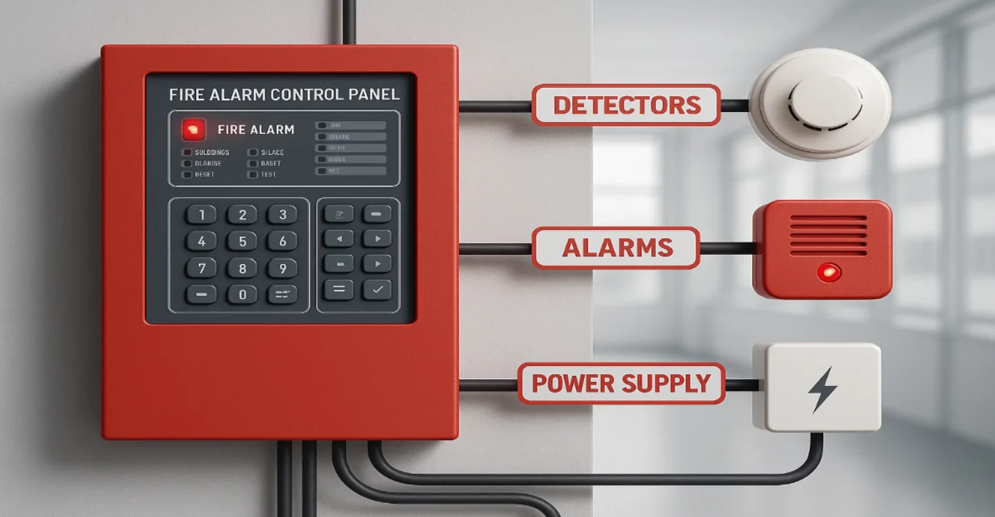
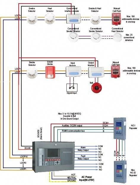
A typical life-safety architecture may include the following elements:
- Smoke, heat or multisensor detectors and manual call points.
- Input and output modules connected to the fire alarm control panel.
- Sounders, strobes and visual alarm devices.
- Voice evacuation or emergency communication controllers and loudspeaker circuits.
- Smoke-control, lift, sprinkler, suppression and building management interfaces.
- Emergency lighting or other critical life-safety interfaces defined by the approved fire strategy.
4. Cable Selection by Circuit and Environment
Cable selection should begin by defining the circuit, route and acceptance evidence. The same product should not be assumed suitable for every part of a fire alarm or emergency communication system.
Detection and Signaling Circuits
Review the following before selecting the cable:
- System-manufacturer cable requirements and circuit topology.
- Route length, conductor-size limitations and terminal compatibility.
- Exposure to electromagnetic interference and segregation from power circuits.
- Containment, mechanical protection and installation environment.
- Project fire-performance requirements and supporting product evidence.
Notification and Emergency Communication Circuits
Notification and voice circuits can require closer attention to connected load and voltage drop. Determine cable size from:
- Circuit voltage and connected current or power.
- Permitted voltage drop and total route length.
- Installation method, ambient conditions and cable grouping.
- Terminal capacity and system-manufacturer limits.
- The required circuit-integrity or fire-performance evidence.
A statement such as “1.5 mm² is suitable for a particular distance” is incomplete unless the load, voltage, route and calculation assumptions are defined.
Ancillary Interfaces and BMS Connections
Connections to smoke control, lifts, access control, sprinkler monitoring, suppression systems, emergency lighting or BMS may have different requirements from detection or notification circuits. Use the approved cause-and-effect matrix and interface drawings to define signal type, supervision, conductor count, shielding, segregation and termination.
5. Heizka Fire-Resistant Cable Family
The table below consolidates the current Heizka product family into one selection view. It adds value beyond a simple product listing by separating shielding choice from conductor size and electrical resistance.
| SKU | Construction | Conductor size | AWG | Stranding | Max. DC resistance at 20°C | Standard pack |
|---|---|---|---|---|---|---|
| HER10S2LZ | Shielded LSZH | 2 × 1.0 mm² | 18 AWG | 16/0.24 mm | 21.4 Ω/km | 500 m/reel |
| HER15S2LZ | Shielded LSZH | 2 × 1.5 mm² | 16 AWG | 30/0.24 mm | 12.33 Ω/km | 500 m/reel |
| HER25S2LZ | Shielded LSZH | 2 × 2.5 mm² | 14 AWG | 49/0.24 mm | 7.98 Ω/km | 500 m/reel |
| HER10U2LZ | Unshielded LSZH | 2 × 1.0 mm² | 18 AWG | 16/0.24 mm | 21.4 Ω/km | 500 m/reel |
| HER15U2LZ | Unshielded LSZH | 2 × 1.5 mm² | 16 AWG | 30/0.24 mm | 12.33 Ω/km | 500 m/reel |
| HER25U2LZ | Unshielded LSZH | 2 × 2.5 mm² | 14 AWG | 49/0.24 mm | 7.98 Ω/km | 500 m/reel |
Product-data note: the matrix uses Heizka first-party product information available at the review date. Shielded variants are described with an overall polyester-tape/aluminium-foil shield and drain wire; unshielded variants omit the metallic shield. Confirm the latest controlled datasheet before quotation or project submission.
How to Use the Heizka Product Matrix
- Choose shielding independently from size. Select shielded or unshielded construction from the system requirement and EMI environment.
- Calculate conductor size. Use current, voltage drop, route length, installation method and equipment terminals; do not select by distance alone.
- Match the exact SKU. The product name, SKU, construction and pack length should agree across the web page, catalogue, datasheet and quotation.
- Request the evidence required by the project. Obtain the exact test report or certificate for the proposed SKU and applicable standard before making a compliance claim.
Explore the Heizka fire-resistant cable range
Use the product category to compare the current shielded and unshielded options, then request the latest controlled datasheet for the selected SKU.
View the Heizka fire-resistant cable category | Download the Heizka product catalogue and datasheets
6. Design and Installation Considerations
Segregation and Routing
Maintain the separation and route shown on approved drawings. Avoid undocumented route changes that can alter circuit length, interference exposure or mechanical risk.
Mechanical Protection
Protect cables from crushing, sharp edges, excessive pulling tension and unsupported spans. Use suitable containment and fixing systems for the route and project requirements.
Screen Termination
For shielded cables, treat the screen and drain wire in accordance with the system manufacturer and approved grounding design. Inconsistent termination can reduce shielding effectiveness or create unwanted current paths.
Bend Radius and Handling
Use the product-specific installation instructions and minimum bend radius. Do not infer handling limits from another cable with a similar diameter.
Joints and Terminations
Minimise unnecessary joints and confirm conductor compatibility with terminals, enclosures and accessories. A cable’s performance can be compromised by unsuitable joints or terminations.
Identification and Records
Maintain cable schedules, route drawings, circuit calculations, material approvals, continuity records, screen-continuity checks, certificates and commissioning documents.
7. Standards and Test Evidence
A standard number on a website or quotation is not sufficient evidence for project approval. The technical reviewer should examine the complete document and confirm that it applies to the exact cable proposed.
What to Verify
- Exact standard number, part and edition.
- Test objective: circuit integrity, flame propagation, smoke density or combustion-gas properties.
- Product name, SKU, conductor size and construction shown in the report.
- Cable overall diameter and test arrangement where relevant.
- Laboratory identity, report number, test date and scope.
- Any limitations, exclusions or installation conditions.
- Consistency among the product page, controlled catalogue, datasheet and commercial submission.
Important Technical Distinction
BS 6387 and the IEC 60331 series address circuit integrity under defined fire-test conditions. IEC 60332-1-2 addresses vertical flame propagation for a single cable. IEC 61034 addresses smoke density, while IEC 60754 addresses halogen-acid-gas and related combustion-gas properties. Evidence for one test objective does not automatically prove another.
8. Heizka Six-Step Selection Workflow
- Define the circuit. Classify it as detection, signaling, notification, voice evacuation, ancillary interface or another critical function.
- Review the environment. Assess routing, containment, interference sources, mechanical exposure, temperature and indoor/outdoor conditions.
- Complete the electrical calculation. Confirm voltage, load, permissible voltage drop, route length, conductor size and terminal compatibility.
- Define the fire-performance requirement. Identify the exact circuit-integrity, flame-propagation, smoke or combustion-gas requirement in the project specification.
- Match the Heizka SKU and evidence. Check the product name, shielding, size and controlled documentation against the proposed SKU.
- Obtain project approval. Submit the complete technical package to the consultant, designer or authorised reviewer before procurement and installation.
9. Heizka Project Submittal Checklist
The following checklist is designed for Heizka project enquiries and consultant submissions. It helps prevent the most common mismatch: quoting one SKU while attaching technical evidence for another.
| Data group | Required information | Status |
|---|---|---|
| Project and system | Project name, building type, fire alarm system manufacturer and circuit function | ☐ Complete |
| Electrical data | System voltage, connected load, route length, permitted voltage drop and terminal limits | ☐ Complete |
| Installation route | Indoor/outdoor, containment, grouping, EMI sources, segregation and mechanical exposure | ☐ Complete |
| Selected cable | Exact Heizka SKU, shielding, conductor size, colour and pack length | ☐ Complete |
| Required evidence | Project standard, exact standard part/edition, certificate or test report and datasheet | ☐ Complete |
| Approval record | Consultant comments, approved sample/submittal revision and final release for procurement | ☐ Complete |
10. Frequently Asked Questions
What type of cable is used for fire alarm circuits?
The correct cable depends on circuit function, equipment requirements, electrical calculations, route conditions and the project’s fire-performance requirement. The exact product must be supported by current documentation and approved for the project.
When should a fire alarm cable be shielded?
Shielding may be considered where the system manufacturer, specification or electromagnetic environment requires it. The termination and grounding method must also be defined.
Does LSZH mean a cable is fire-resistant?
No. LSZH relates to smoke and halogen-related material properties under defined tests. It does not by itself prove circuit integrity or resistance to flame propagation.
What is the difference between circuit integrity and flame retardancy?
Circuit integrity concerns continued circuit operation under a defined fire test. Flame-propagation testing evaluates how flame travels along a cable. These are different test objectives.
How should 1.0 mm², 1.5 mm² and 2.5 mm² cables be selected?
Select conductor size from circuit current, permissible voltage drop, route length, installation method, terminal compatibility and the system design. Do not select from route length alone.
Can the same cable be used for detection, notification and voice evacuation circuits?
Possibly, but it should not be assumed. Each circuit can have different load, signal, shielding and circuit-survivability requirements.
Which documents should accompany a Heizka project submission?
Use the current product datasheet, controlled catalogue, SKU-specific test reports or certificates, compliance schedule, circuit calculations, installation information and a clear mapping between the proposed SKU and specification.
Why must the exact IEC 60331 part be checked?
The IEC 60331 series contains different test arrangements. The appropriate part can depend on cable diameter and how the cable is tested. The report must identify the exact part that applies to the proposed cable.
11. Request Technical Support or a Quotation
Choosing a fire alarm cable requires coordination among the system design, electrical calculation, installation route and verified product evidence. Heizka can review the project information and identify product options for consultant or system-designer approval.
Send Your Specification for Review
Include the project name, circuit function, system manufacturer, voltage, connected load, route length, shielding requirement, installation environment, required standard and requested technical documents.
Send your specification and request a quote | Request Heizka technical support
12. Sources and Technical Review Record
Technical review completed on 02 August 2026 using the sources below. This article intentionally avoids claiming that every Heizka SKU complies with a named standard unless the claim is supported by the latest product-specific test evidence.
- Heizka Fire-Resistant Cable category: Heizka fire-resistant cable product family — First-party product-family reference.
- Heizka Shielded LSZH 2 × 2.5 mm²: Heizka Fire Resistant Cable Shielded, LSZH 2×2.5mm² — First-party SKU, construction and technical-value reference.
- Heizka Unshielded LSZH 2 × 2.5 mm²: Heizka Fire Resistant Cable Unshielded, LSZH 2×2.5mm² — First-party unshielded family and comparison reference.
- Heizka Unshielded LSZH 2 × 1.5 mm²: Heizka Fire Resistant Cable Unshielded, LSZH 2×1.5mm² — First-party SKU and technical-value reference.
- BS 6387:2013: BSI record for BS 6387 — Primary source for the standard title and scope.
- IEC 60331-1:2018: IEC Webstore record for IEC 60331-1:2018 — Primary source for circuit-integrity testing of cables exceeding 20 mm overall diameter.
- IEC 60331-2:2018: IEC Webstore record for IEC 60331-2:2018 — Primary source for circuit-integrity testing of cables not exceeding 20 mm overall diameter.
- IEC 60332-1-2:2025: IEC Webstore record for IEC 60332-1-2:2025 — Primary source for single-cable vertical flame-propagation testing.