Security systems fail on the boring half of the design. The camera specification is agreed, the access control platform is chosen, the head-end is sized — and then a door strike chatters at the far end of a corridor because nobody calculated voltage drop, a bundle of PoE cameras runs hot inside a sealed containment, or a reader cable is pulled beside a motor feed and the credential reads become intermittent.
This guide gives security integrators, electrical contractors and consultants a selection framework for the cabling behind IP surveillance, access control, intrusion detection and intercom systems. It separates the two cable paths that are routinely confused: the data and PoE path, and the power and signaling path. Each has different failure modes and different selection rules.
Request a Security Cabling Review
Send the device schedule, run lengths, PoE class per device, door hardware currents, containment route and applicable project specification for technical review.
Send your security cabling requirements to the Heizka technical team
1. Solution Overview
A security installation is not one cabling system. It is several subsystems sharing a route, each with its own electrical and environmental requirement. Treating them as one specification is the most common cause of rework on site.
| Subsystem | What the cabling has to do | Characteristics to evaluate |
|---|---|---|
| IP video surveillance | Carry Ethernet data and PoE power to each camera over a single channel. | Category and channel length, PoE class and conductor heating, bundle size, shielded or unshielded, outdoor exposure. |
| Access control door hardware | Deliver stable DC to strikes, maglocks and readers, and return supervised signals. | Conductor cross-section, voltage drop over the actual run, inrush behavior, shielding, conductor count per door. |
| Intrusion detection | Connect detectors, contacts and sounders to the panel with supervised loops. | Signal type, end-of-line supervision, interference exposure, segregation from power. |
| Intercom and audio | Carry balanced or unbalanced audio and, in IP systems, Ethernet with PoE. | Shielding, pair count, grounding method, and whether the platform is IP or analog. |
| Head-end and equipment room | Terminate, patch, power and protect recorders, controllers and switches. | Rack footprint and load, patching density, power continuity and runtime, cable management. |
| Life-safety interfaces | Release doors on a fire signal and pass supervised status to the fire alarm system. | A different cable family with its own circuit-integrity requirement — see the fire alarm guide below. |
Engineering note: this table is a planning framework, not a substitute for the device schedule, the manufacturer wiring instructions, the electrical calculations or the approved project drawings.
2. Two Cable Paths, Not One
Almost every problem on a security job traces back to one of two paths being specified with the other path’s logic.
| Data and PoE path | Power and signaling path | |
|---|---|---|
| Serves | IP cameras, IP intercoms, IP door controllers, wireless access points. | Electric strikes, maglocks, readers, request-to-exit devices, detectors, contacts, sounders, sensors. |
| Cable | Balanced twisted pair — CAT5E through CAT7A, selected by PoE class and channel length. | Multi-conductor shielded control cable, selected by current and voltage drop, not by bandwidth. |
| What limits the run | The 100 m channel limit, and conductor heating when many powered cables share a bundle. | Voltage drop at the device under its holding and inrush current. |
| Typical failure | Link drops or PoE renegotiation under thermal load; alien crosstalk in dense bundles. | Device operates on the bench and chatters or fails to release at the end of the run. |
| Heizka range | Copper cabling systems, CAT5E to CAT7A | Security and control cable, 14 to 18 AWG shielded |
A note on scope: Heizka does not currently list coaxial cable, so analog CCTV retrofits on RG-59 or RG-6 are outside the published range. New and converted installations on IP cameras are served by the copper cabling systems above.
3. PoE: What Actually Limits the Run
The 100 m channel limit is a data limit and it has not changed. What has changed is how much power now travels the same conductors, and power is what turns a compliant channel into a marginal one.
| Standard | Type | PSE output | Available at the device | Pairs used |
|---|---|---|---|---|
| IEEE 802.3af | Type 1 | 15.4 W | about 12.95 W | 2 |
| IEEE 802.3at | Type 2 | 30 W | about 25.5 W | 2 |
| IEEE 802.3bt | Type 3 (Class 5–6) | 60 W | up to about 51 W | 4 |
| IEEE 802.3bt | Type 4 (Class 7–8) | 90 W | about 71–73 W | 4 |
Heat Is the Real Constraint
A single PoE camera on a single cable is not a thermal problem. Forty of them in one bundle inside a closed containment, in a warm ceiling void, is. Conductor temperature rises with the square of the current and with bundle size, and insertion loss rises with temperature — so the channel that passed certification at 20 °C can fail under load in service.
Three levers control this, and they should be decided at design stage rather than discovered at commissioning:
- Conductor size. A larger conductor cross-section carries the same current at a lower temperature rise. This is the main reason CATEGORY 6A is specified for high-class PoE devices rather than the minimum category that meets the data requirement.
- Bundle size. Smaller bundles shed heat better. Splitting one large bundle into several smaller ones is usually cheaper than upgrading the cable.
- Installation environment. Ambient temperature, containment fill and whether the route is enclosed all change the outcome. Confirm the derating basis used in the design.
TIA TSB-184-A addresses cabling guidelines for remote powering and is the reference to consult for bundle and temperature guidance. Confirm the current edition and its applicability with the project specification.
The Code Requirement in the United States
Cables that transmit power and data together are subject to an ampacity and bundling requirement in the National Electrical Code, historically located at 725.144. The 2023 NEC restructured this area: a new Article 722, Cables for Power-Limited Circuits and Fault-Managed Power Circuits, was created, Article 725 was retitled Class 2 and Class 3 Power-Limited Circuits, and Class 1 circuits moved to a new Article 724. Cables marked Class 2-LP or Class 3-LP carry a marked current limit per conductor that provides an alternative compliance path.
Because jurisdictions adopt different NEC editions, confirm the exact article and section number in the edition adopted for the project rather than quoting a section number from memory.
4. Voltage Drop on Door Hardware and Field Devices
On the power and signaling path, bandwidth is irrelevant and voltage drop decides everything. A 12 V device with a 10 percent tolerance has about 1.2 V of margin for the entire round trip, and a long run to a high-current strike consumes it quickly.
The Calculation
For a two-conductor DC run, the drop is:
Vdrop = 2 × L × R × I
where L is the one-way run length in kilometers, R is the conductor resistance in ohms per kilometer taken from the product datasheet, and I is the device current in amperes. The factor of two accounts for the return conductor.
Worked Example
Heizka publishes a maximum DC resistance of 8.2 Ω/km at 14 AWG. For a 50 m run to a device drawing 0.5 A:
Vdrop = 2 × 0.05 km × 8.2 Ω/km × 0.5 A = 0.41 V
Comfortable on a 12 V circuit. Double the run and the current, however, and the same conductor gives 1.64 V — outside the tolerance of most 12 V hardware. The variables that matter are length and current, not the label on the box.
What to Confirm Before Sizing
- Holding current and inrush. Take both from the device manufacturer. Sizing on holding current alone can leave a strike that will not actuate reliably.
- Whether several devices share a run. Currents add, and the drop is calculated on the total.
- The actual routed length, including risers, containment detours and service loops — not the distance measured on the floor plan.
- The resistance value for the specific conductor size from the current datasheet, since 16 AWG and 18 AWG differ substantially from the 14 AWG figure above.
- The device voltage tolerance and whether the power supply is local to the door or centralized.
A statement such as “18 AWG is fine up to 100 m” is incomplete unless the current, voltage and tolerance are stated with it.
5. Shielding, Interference and Grounding
Security cabling shares risers and trays with lighting circuits, elevator machinery, variable-frequency drives and switched-mode power supplies. Reader data lines, supervised loops and analog audio are all susceptible to the resulting interference.
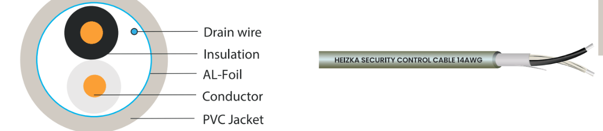
The Heizka control cable range uses an aluminum foil screen with a drain wire. The screen only works if it is terminated correctly, and incorrect termination is worse than no screen at all:
- Ground at one end only unless the system manufacturer specifies otherwise. Grounding both ends can create a ground loop that injects the very noise the screen was meant to exclude.
- Terminate the drain wire deliberately. A screen left floating in the enclosure provides no benefit and can act as an antenna.
- Keep the untwisted and unscreened length short at the termination. A generous service loop with the screen stripped back defeats the construction.
- Maintain separation from power circuits in accordance with the adopted code and the approved drawings. Separation is the first defense; shielding is the second.
Unshielded cable can be entirely appropriate where the route is clean and the system manufacturer permits it. Shielding should be a decision, not a reflex.
6. Heizka Security and Control Cable Family
The current range is six multi-conductor shielded cables, separating conductor size from pair count so the two can be selected independently.
| Product | Conductor size | Pairs | Typical use |
|---|---|---|---|
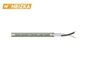
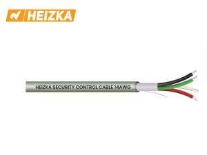
| 14AWG Shielded Cable | 14 AWG | 1 pair | Longer runs and higher-current door hardware where voltage drop governs. |
| 14AWG Shielded Cable 2 Pair | 14 AWG | 2 pairs | Power and signal to the same door position in one cable. |
| 16AWG Shielded Cable | 16 AWG | 1 pair | Moderate runs to strikes, maglocks and powered devices. |
| 16AWG Shielded Cable 2 Pair | 16 AWG | 2 pairs | Combined power and supervised signal runs. |
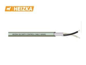
| 18AWG Shielded Cable 1 Pair | 18 AWG | 1 pair | Low-current signaling, contacts, detectors and reader data. |
| 18AWG Shielded Cable 2 Pair | 18 AWG | 2 pairs | Two low-current circuits to the same field position. |

Published Construction
- Conductor: tinned copper at 14 AWG; bare copper, stranded or solid, at 16 and 18 AWG.
- Insulation: HDPE.
- Screen: aluminum foil with drain wire.
- Jacket: gray PVC, 0.6 mm average.
- Rating: 300 V.
- Packaging: 305 m per box with sequential length markings.
- Published resistance: 8.2 Ω/km at 14 AWG.
Product-data note: these figures come from Heizka first-party product pages at the review date. Confirm the current controlled datasheet for the specific product before quotation or project submittal, and obtain resistance values for 16 AWG and 18 AWG from that datasheet rather than interpolating.
Compare the range and download the data
View the Heizka security and control cable category | Download datasheets and the product catalog
7. Copper Cabling for Cameras and IP Devices
On the data and PoE path, the category is selected from the PoE class and the thermal environment, not only from the data rate the camera needs today.
| Situation | Consideration | Heizka range |
|---|---|---|
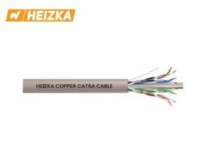
| Low-class PoE, short runs, small bundles | Meets the data requirement with margin; verify the thermal case before defaulting to the minimum category. | CAT5E and CAT6 systems |
| Type 3 and Type 4 PoE, dense bundles, warm voids | Larger conductor cross-section lowers temperature rise at the same current. | CAT6A and CAT7A systems |
| Routes alongside power or machinery | A screened construction where the route or specification calls for it, with a defined grounding method. | CAT6 F/UTP within the copper range |
| Termination and patching | Channel performance is a property of the complete link, so components should be selected as a system. | Copper patch panels, jacks and cords |
Whatever the category, the installed channel should be verified by field test. Component datasheets describe components; they do not certify the link that was actually pulled, terminated and dressed on site.
8. Head-End, Patching and Power Continuity
The head-end is where a security system is judged during handover, and where the consequences of an undersized enclosure appear first.
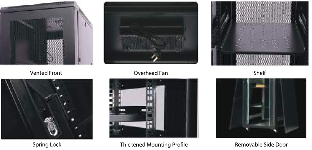
- Depth before height. Recorders and video management servers are deep, and the bend radius behind them is real. A 600 mm-deep cabinet that suited a patch-only position will not suit a recorder position.
- Thermal load. Recorders and PoE switches dissipate continuously. Confirm ventilation and ambient temperature, not just rack units.
- Runtime, not just backup. Decide how long cameras, switches, controllers and recorders must remain powered, then size accordingly — a UPS that outlasts the recorder but not the PoE switch protects nothing.
- Door hardware behavior on power loss. Fail-safe and fail-secure decisions are life-safety decisions and belong with the approved fire strategy, not with the power schedule.
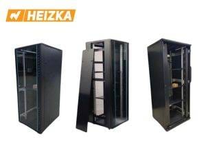
The Heizka range covers 27U to 47U server rack cabinets and wall-mount enclosures for satellite positions, with lithium-ion and VRLA lead-acid UPS ranges. The two battery chemistries differ in footprint, weight, service life and thermal behavior, so the choice is a facilities decision as much as a capital one.
9. Listing, Fire Performance and Penetrations
Security cable is often the last package specified and the first to be installed through a fire-rated wall. Three points deserve attention before procurement.
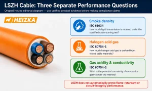
Cable listing for the space. Plenum, riser and general-purpose spaces call for different listings. The Heizka control cable range is published with a gray PVC jacket; where a project requires a plenum or riser listing, or a low smoke zero halogen jacket, confirm the specific listing with the technical team rather than assuming it from the family.
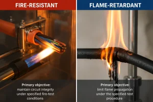
Control cable is not fire-resistant cable. Circuit integrity under fire is a separate test objective with its own product family. Where a security circuit must keep operating during a fire — a door release or an interface to the fire alarm system — that circuit belongs with the fire-resistant cable range, and the distinction is explained in fire-resistant versus flame-retardant cable. Jacket material is a further and separate question, covered in what LSZH cable actually means.
Penetrations. A firestop system is tested as an assembly: barrier type, opening size, cable fill and sealing product together. Adding cables to an existing penetration after handover can invalidate the tested configuration.
10. Seven-Step Selection Workflow
- Build the device schedule. List every camera, reader, lock, detector and intercom with its location, and mark which path it sits on.
- Record the electrical demand. PoE class per IP device; holding and inrush current per powered device from the manufacturer.
- Measure the real routes. Routed lengths including risers and service loops, plus containment fill and bundle sizes.
- Size the data path. Category from PoE class and thermal environment, checked against the 100 m channel limit and the derating basis.
- Size the power path. Voltage drop calculated from the datasheet resistance at the actual current and length, against the device tolerance.
- Settle listing and fire performance. Space listing, separation from power, penetration treatment, and which circuits require fire-resistant cable instead.
- Assemble the submittal. Map each proposed product to the specification clause it satisfies, with the current datasheet attached.
11. Project Submittal Checklist
| Data group | Required information | Status |
|---|---|---|
| Project and systems | Project name, building type, security platform manufacturers, governing code edition | ☐ Complete |
| Device schedule | Cameras, readers, locks, detectors and intercoms with locations and quantities | ☐ Complete |
| Electrical data | PoE class per device, holding and inrush current per powered device, supply voltage and tolerance | ☐ Complete |
| Routes | Routed lengths, bundle sizes, containment type and fill, ambient temperature, interference sources | ☐ Complete |
| Selected cable | Exact product, conductor size, pair count, shielding, jacket listing and pack length | ☐ Complete |
| Head-end | Rack width, depth, U height and load; UPS load and required runtime per subsystem | ☐ Complete |
| Evidence | Current datasheets, listing evidence where required, clause-by-clause mapping, approval record | ☐ Complete |
12. Frequently Asked Questions
What cable should be used for an IP security camera?
Balanced twisted-pair cable selected from the PoE class, the routed length against the 100 m channel limit, and the thermal environment of the bundle. Higher categories are frequently specified for high-class PoE because the larger conductor runs cooler, not because the camera needs the extra bandwidth.
How far can a PoE camera run?
The data channel limit is 100 m and has not changed. Whether the run performs at that length depends on the PoE type, the bundle size, the ambient temperature and the installation method. A run that certifies on a cold morning can behave differently under full load in a warm ceiling void.
Why does a door strike work on the bench but not at the door?
Almost always voltage drop. Calculate it from the datasheet resistance at the device inrush current over the actual routed length, and compare the result against the device voltage tolerance rather than its nominal voltage.
Should security cable be shielded?
Shield where the route, the system manufacturer or the specification calls for it, and define the grounding method at the same time. Ground the screen at one end only unless instructed otherwise; a screen terminated at both ends can create a ground loop that makes interference worse.
Can one cable serve both the lock and the reader at a door?
A two-pair construction is often used for exactly this, but the pairs must be sized independently: the lock pair is sized by current and voltage drop, the signal pair by the reader requirement. Confirm the arrangement against the access control manufacturer wiring instructions.
Is control cable acceptable for circuits that must survive a fire?
No. Circuit integrity under fire is a separate test objective served by fire-resistant cable. Any security circuit required to operate during a fire scenario should be identified in the fire strategy and cabled accordingly.
Does Heizka supply coaxial cable for analog CCTV?
The current published range does not include coaxial cable. Analog retrofits on RG-59 or RG-6 fall outside it; IP installations are served by the copper cabling systems.
Which documents should accompany a Heizka security cabling submittal?
The current datasheet for each proposed product, the controlled catalog, listing evidence where the specification requires it, the device schedule with electrical data, voltage drop calculations, and a clear mapping between each product and the specification clause it satisfies.
13. Request Technical Support or a Quotation
Security cabling decisions interlock: the PoE class drives the category, the category drives bundle behavior, the door hardware current drives the conductor size, and the listing requirement drives which of those choices is even permitted in the space. Heizka can review the project information and identify product options for consultant or designer approval.
Send Your Specification for Review
Include the project name, governing code edition, device schedule, PoE class per device, door hardware currents and voltage tolerance, routed lengths and bundle sizes, containment and space listing requirements, head-end layout and required runtime.
Send your specification and request a quote | Request Heizka technical support
14. Sources and Technical Review Record
Technical review completed on 23 August 2026 using the sources below. This guide intentionally avoids claiming that any Heizka product complies with a named standard or listing unless the claim is supported by current product-specific documentation. Code summaries are drawn from published commentary and must be confirmed against the edition adopted for the project.
- IEEE 802.3bt power levels: Fluke Networks, Type 3 and Type 4 are here — Source for Type 3 and Type 4 classes and available power at the device.
- 2023 NEC restructure: Cabling Installation & Maintenance, Revisions to cable requirements in the 2023 National Electrical Code — Source for the creation of Article 722, the retitling of Article 725 and the move of Class 1 circuits to Article 724.
- Transmission of power and data: Ethernet Alliance, Cabling-system design and installation for delivering power via PoE — Background on bundling, temperature rise and the code treatment of cables carrying power and data.
- Heizka security and control cable: Heizka security and control cable system — First-party construction, resistance and packaging reference.
- Heizka copper cabling: Heizka copper cabling systems — First-party category and construction reference.
- Heizka rack cabinets: Heizka rack cabinet range — First-party footprint and load rating reference.
- Related solution: Fire Alarm and Emergency Communication Cabling Solutions — Companion guide for circuits that must survive a fire.
- Related solution: Data Center Cabling Infrastructure Solutions — Companion guide for the head-end and backbone side of the same building.
- Related guidance: What Is LSZH Cable and Where Should It Be Used? — Companion article on jacket material properties and their limits.