Data centre and edge computing projects fail on cabling far more often than on active equipment. The switches arrive specified correctly; the trouble starts with pathway fill that leaves no room for the second phase, patch panels chosen before the connector policy was agreed, cabinets ordered at a width the current standard no longer permits in a distributor area, and a fibre loss budget consumed at the connections rather than in the cable.
This guide gives consultants, contractors, system integrators and data centre operators a selection framework for the passive layer: media choice per link type, fibre and copper plant, pathways and containment, cabinets, and power continuity at the rack. It is organised around the spaces defined in ANSI/TIA-942 rather than around a product list, because the space determines the requirement.
Request a Data Centre Cabling Review
Send the space schedule, link types and quantities, required channel performance, connector policy, containment route, cabinet layout and applicable project specification for technical review.
Send your data centre cabling requirements to the Heizka technical team
1. Solution Overview
ANSI/TIA-942 organises a data centre into functional spaces. Each space carries a different cabling requirement, and treating them as one homogeneous requirement is the most common cause of specification drift between design and procurement.
| Space | What the cabling has to do there | Characteristics to evaluate |
|---|---|---|
| Entrance room (ER) | Terminate carrier and campus circuits and hand off to the main distribution area. | Outdoor-rated or armoured construction, transition to indoor-rated cable, splice housing, demarcation ownership. |
| Main distribution area (MDA) | Central cross-connect for the whole facility. Highest fibre density and the least tolerance for rework. | Patch panel density per rack unit, connector policy, cabinet width, pathway capacity for future phases. |
| Intermediate and horizontal distribution areas (IDA / HDA) | Distribute backbone toward equipment rows and terminate horizontal cabling. | Fibre count per row, copper channel performance, cabinet width, cable management and bend radius control. |
| Zone distribution area (ZDA) | Optional interconnect point in the horizontal, used where equipment moves frequently. | Whether the project design permits a ZDA at all, and the channel budget consumed by the extra connection. |
| Equipment distribution area (EDA) | Terminate at the equipment outlet in the equipment cabinet or rack. | Connector type required at the outlet, patch cord length discipline, airflow obstruction, power distribution. |
| Support and building systems | Fire detection, access control, environmental monitoring and building management. | Separate cable families with their own fire-performance and signalling requirements. |
Engineering note: this table is a planning framework, not a substitute for the approved design drawings, the channel calculations or the connector policy agreed with the operator.
2. What Changed in ANSI/TIA-942-C
ANSI/TIA-942-C was published in May 2024 and supersedes the B revision. Several of its changes affect procurement decisions directly, not just design documents. If a project specification still cites the B revision, the discrepancy is worth raising before cabinets and connectivity are ordered.
| Change in the C revision | Why it matters at procurement |
|---|---|
| Cabinets in the MDA, IDA and HDA must be a minimum of 800 mm wide | A 600 mm cabinet that was acceptable under earlier practice may no longer suit a distributor area. Check the width against the space, not against the rack elevation alone. |
| Very small form factor (VSFF) connectors permitted outside the equipment outlet | Distributor and entrance spaces are no longer restricted to LC and MPO. The equipment outlet remains the space where LC and/or MPO are required. |
| Minimum of two Category 6A or higher horizontal runs to wireless access points | Affects horizontal quantities and patch panel port counts in facilities with a wireless overlay. |
| Minimum of two optical fibres recommended for horizontal and backbone cabling | Sets a floor, not a target. Fibre count should still be driven by the growth plan and pathway capacity. |
| Single-pair Ethernet (SP1-400, SP1-1000) and broadband coaxial cable recognised | Opens IoT sensing and video distribution as recognised media rather than exceptions requiring justification. |
| Micro edge data centre (µEDC) classification, Type A and Type B | Gives small edge deployments a defined vocabulary, which helps when a specification written for a hyperscale facility is being applied to an edge cabinet. |
Standards note: the summary above is drawn from the published commentary listed in section 14. Confirm every clause against the purchased copy of ANSI/TIA-942-C before making a compliance claim in a submittal. Projects in Europe and parts of Asia may additionally be governed by the ISO/IEC 11801 series for generic cabling and the EN 50600 / ISO/IEC 22237 series for facility infrastructure; confirm the current edition applicable to the project.
3. Media Selection by Link Type
Media choice should follow the link, the distance and the equipment interface, in that order. Selecting a media type facility-wide and then forcing every link into it is what produces both stranded capacity and late redesign.
| Link | Typical media consideration | Questions to settle first |
|---|---|---|
| Carrier entrance to MDA | Singlemode (OS2), often outdoor or armoured construction into the entrance room. | Route exposure, rodent and mechanical risk, transition point to indoor-rated cable, splice versus pre-terminated. |
| MDA to IDA / HDA backbone | Singlemode for reach and technology headroom; multimode where the equipment optics and distances suit it. | Optics already selected? Distance? Expected refresh cycle? Pathway capacity for a second phase? |
| Row distribution to equipment cabinets | Fibre trunks with panel terminations, or balanced twisted pair depending on the interface. | Port counts per cabinet, cabinet-level patching strategy, airflow impact of cable volume. |
| Horizontal to equipment outlet | Category 6A or higher balanced twisted pair for 10GBASE-T and wireless overlay. | Channel length, alien crosstalk in dense bundles, shielded versus unshielded, PoE thermal loading. |
| Building systems and IoT sensing | Control and instrumentation cable, or single-pair Ethernet where recognised by the design. | Signal type, segregation from power, fire-performance requirement for the space. |
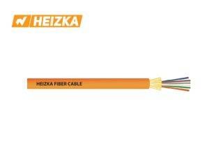
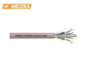
Heizka supplies both media families. The indoor tight-buffered fibre range is offered in OS2, OM2, OM3 and OM4 grades with an LSZH jacket; outdoor stranded loose-tube construction is available in all-dielectric and steel-tape armoured versions. The copper range covers CAT5E through CAT7A, including a CAT6 F/UTP option where a screened construction is specified. Heizka does not currently list OM5 fibre, so a specification requiring OM5 should be raised with the technical team rather than assumed.
Compare the media families
Heizka fibre optic cable range | Heizka copper cabling systems | Download datasheets and the product catalogue
4. Fibre Plant: The Loss Budget Is Spent at the Ends
On a finished fibre link, attenuation in the cable itself is usually the smallest and most predictable term. The connections dominate. A design that specifies premium cable and then leaves connector grade, adaptor quality and splice method undefined has not controlled its loss budget.
Build the Budget Before Choosing Products
- Count every mated pair in the channel, including any zone distribution point.
- Apply the insertion loss allowance for each connection from the component documentation, not from a generic figure.
- Add splice loss where fusion or mechanical splices are used.
- Compare the total against the optical power budget of the transceivers actually specified.
- Keep margin for future re-patching, cleaning degradation and one additional connection.
Heizka Fibre Termination Range
| Component | Options | Published performance |
|---|---|---|
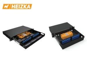
| Rack-mount patch panels | 1U, 2U, 3U and 4U; sliding tray or integrated splice tray variants (HEAOU241A, HEAOU481S, HEAOU962S, HEAOU1443S, HEAOU2884). | Capacity scales from 24 simplex SC/ST/FC positions at 1U to 144 at 4U, or the equivalent duplex LC count. Confirm the exact port count per model on the controlled datasheet. |
| Ceramic-sleeve adaptors | Simplex SC footprint and duplex LC footprint; singlemode and multimode; PC, UPC and APC polish. | Insertion loss ≤ 0.2 dB singlemode and ≤ 0.1 dB multimode; minimum 500 mating cycles. |
| Patch cords and pigtails | ST, SC, LC and FC in PC, UPC and APC; simplex or duplex cords, simplex pigtails; OM2, OM3, OS2 and G657A; LSZH jacket. | Insertion loss ≤ 0.3 dB singlemode and ≤ 0.2 dB multimode. |
Product-data note: figures above are taken from Heizka first-party product pages at the review date. Port counts, polish availability and loss grades must be confirmed against the current controlled datasheet for the specific model before quotation or submittal.
Connector Policy Is a Project Decision
Under the C revision, spaces other than the equipment outlet may use very small form factor connectors, which changes the density arithmetic in the MDA. The equipment outlet still requires LC and/or MPO. Fix the connector policy per space early: it determines panel selection, patch cord inventory, test equipment adaptors and the spares held for the life of the facility.
5. Copper Plant: Category 6A and Above
Category 6A is the practical baseline for 10GBASE-T horizontal links and is the grade the C revision names for wireless access point runs. Three factors decide whether a Category 6A installation performs to its channel specification.
- Alien crosstalk. Dense parallel bundles are the usual cause of failure. Bundle discipline and, where specified, a screened construction address it.
- Channel length and connection count. Every additional connection in the channel consumes margin. A zone distribution point must be included in the calculation.
- Power over Ethernet thermal loading. Bundle size, ambient temperature and installation method affect conductor temperature and therefore insertion loss. Confirm the derating basis used in the design.
The Heizka copper range includes CAT6A and CAT7A systems alongside CAT5E and CAT6, with a screened CAT6 F/UTP option. Matching patch panels, keystone jacks and cords are listed under copper accessories. Channel performance is a property of the complete link, so components should be selected as a system and the installed channel verified by field test rather than inferred from component datasheets.
6. Pathways and Containment
Pathway capacity is where growth plans are quietly lost. A containment route sized for day-one fibre counts leaves no route for the second phase, and the cost of adding containment in a live white space is far higher than sizing it correctly at the start.
Heizka Fibre Raceway System
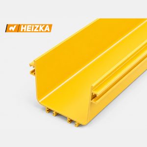
The Heizka fibre raceway is an enclosed PVC channel with a snap-on cover and a full fitting range for corners, tees, crosses, level changes and cabinet entry. It is intended for indoor use in data centres and telecommunication facilities.
| Series | Item no. | W × H × L (mm) | Typical use |
|---|---|---|---|
| 60 | 3A100 | 60 × 60 × 1000 | Cabinet drops and short spurs. |
| 120 | 3A300 | 120 × 100 × 2000 | Row-level distribution at low fibre counts. |
| 150 | 3A400 | 150 × 100 × 2000 | Row-level distribution. |
| 240 | 3A600 | 240 × 100 × 2000 | Aggregation between rows. |
| 300 | 3A700 | 300 × 100 × 2000 | Aggregation toward the distribution area. |
| 360 | 3A800 | 360 × 100 × 2000 | Main runs in medium facilities. |
| 600 | 3A900 | 600 × 100 × 2000 | Main trunk routes at high fibre density. |
Channel and cover are PVC and the fittings are produced in PVC and ABS. The system is supplied in yellow as standard, is stated as UL94 V-0 self-extinguishing and RoHS compliant, and maintains a minimum 30 mm bend radius through the fittings.
Sizing the Route
- Count day-one fibre, then add the growth plan. Size the route for the planned end state, not the first phase.
- Apply a fill limit, not a geometric maximum. A channel filled to its cross-sectional area cannot be worked on later and makes bend radius impossible to control.
- Check the bend radius at every fitting. The pathway must respect the minimum bend radius of the cable it carries, which may be greater than the pathway own 30 mm figure.
- Plan the exits. Spillout, trumpet and movable exit fittings determine how cable leaves the route into a cabinet without a stress point.
- Confirm the fire and code requirement for the space. Material ratings and installation environment are set by the project specification and the authority having jurisdiction.
Plan the pathway before the fibre count is final
View the Heizka fibre raceway system and fittings | Send your row layout for a containment sizing review
7. Cabinets: The 800 mm Rule
The C revision sets a minimum cabinet width of 800 mm in the main, intermediate and horizontal distribution areas. This is a genuine procurement change, because 600 mm cabinets remain entirely appropriate in other spaces and are frequently ordered by habit for distributor areas as well.
| Heizka option | Heights and footprint | Where it fits |
|---|---|---|
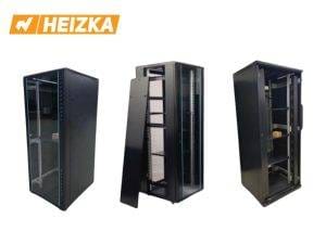
| Server rack cabinets | 27U to 47U (1400–2200 mm frame), footprints from 600 × 600 mm to 800 × 1000 mm, 800–1000 kg load rating. | Specify the 800 mm-wide footprint for MDA, IDA and HDA positions under the C revision. The 600 mm-wide options remain suitable for equipment areas where the project design permits. |
| Server rack cabinets, D series | 45U heavy-duty construction, 2.5 mm base and 1.2 mm panels, load rating up to 1800 kg. | High-density or heavy equipment positions where the standard load rating is insufficient. |
| Wall-mount cabinets, T and W type | Wall-mounted enclosures. | Edge cabinets, satellite rooms and telecommunication spaces outside the main white space. |
Frames are SPCC cold-rolled steel with a 2.0 mm mounting profile and 1.0–1.2 mm panels, with top and bottom cable entry and an S-shaped mounting profile adjustable fore and aft. Heizka states conformity of the rack dimensions to ANSI/EIA RS-310-D, IEC 297-2 and DIN 41491. Confirm the exact model, footprint, load rating and accessory list against the controlled datasheet before order.
Depth deserves as much attention as width. Deep switches with rear-mounted power supplies, plus the bend radius needed behind them, routinely defeat a 600 mm-deep cabinet that looked adequate on the elevation drawing.
8. Power Continuity at the Rack
Cabling and power continuity are usually procured by different parties, which is why a rack layout can be finalised before anyone has confirmed that the UPS footprint fits the row. Settle the following alongside the cabinet schedule rather than after it.
- Load and runtime. Connected load, required autonomy and the recharge time acceptable to the operations team.
- Battery chemistry. Heizka offers both lithium-ion and VRLA lead-acid ranges. The two differ in footprint, weight, expected service life, thermal behaviour and disposal handling; the choice is a total-cost and facilities decision, not only a capital one.
- Floor loading and placement. Battery weight against the structural allowance, and the ventilation or containment the chemistry requires.
- Monitoring integration. How UPS status reaches the building management or DCIM platform, and over which cable family.
Confirm electrical ratings, topology and runtime figures for a specific model with the Heizka technical team, since the published range varies by region.
9. Heizka Product Map for Data Centre Projects
| Requirement | Heizka range |
|---|---|
| Backbone and horizontal fibre | Indoor tight-buffered LSZH; outdoor loose tube, all-dielectric or steel-tape armoured; OS2, OM2, OM3, OM4 |
| Fibre termination and patching | 1U–4U patch panels, ceramic-sleeve adaptors, factory-terminated cords and pigtails |
| Balanced twisted-pair horizontal | CAT5E, CAT6, CAT6 F/UTP, CAT6A, CAT7A systems |
| Copper termination | Patch panels, jacks and cords |
| Fibre pathways and containment | Enclosed PVC raceway, 60 × 60 mm to 600 × 100 mm, with full fitting range |
| Cabinets and enclosures | 27U–47U server cabinets, heavy-duty D series, wall-mount T and W types |
| Power continuity | Lithium-ion and VRLA lead-acid UPS ranges |
| Building systems and life safety | Security and control cable; fire-resistant cable for detection and emergency communication circuits |
10. Seven-Step Selection Workflow
- Fix the space schedule. Identify the entrance room, distribution areas and equipment areas, and record which revision of the standard governs the project.
- Define the links. List every link type with its distance, interface and quantity, day one and at the planned end state.
- Set the connector policy per space. Decide before selecting panels, because it determines density, cords, test adaptors and spares.
- Calculate the budgets. Optical loss budget against the specified transceivers; copper channel performance including every connection.
- Size the pathways for the end state. Apply a fill limit and verify bend radius at every fitting.
- Confirm cabinet width, depth and load. Check the 800 mm minimum where it applies and the depth against the deepest specified equipment.
- Assemble the submittal. Map each proposed SKU to the specification clause it satisfies, with the current datasheet attached, before procurement.
11. Project Submittal Checklist
This checklist is designed for Heizka data centre enquiries and consultant submissions. It targets the most common mismatch: a bill of materials priced against one revision of the specification and documented against another.
| Data group | Required information | Status |
|---|---|---|
| Project and governing standard | Project name, facility type, governing standard and revision, certification target if any | ☐ Complete |
| Space schedule | Entrance room, MDA, IDA, HDA, ZDA and EDA positions with cabinet counts per space | ☐ Complete |
| Link schedule | Link types, distances, quantities day one and at end state, transceiver optics specified | ☐ Complete |
| Connectivity policy | Connector type per space, polish, panel density, pre-terminated versus field-terminated | ☐ Complete |
| Pathways | Route drawings, fibre counts, fill limit applied, fitting schedule, bend radius check | ☐ Complete |
| Cabinets and power | Width, depth, U height, load rating, deepest equipment, UPS load and runtime | ☐ Complete |
| Evidence | Current datasheets for each proposed SKU, test reports where required, clause-by-clause mapping | ☐ Complete |
12. Frequently Asked Questions
Which standard governs data centre cabling?
In North America and in many international projects, ANSI/TIA-942 is the reference for data centre telecommunications infrastructure, with the C revision published in May 2024. Projects in Europe and parts of Asia may instead or additionally reference the ISO/IEC 11801 series for generic cabling and the EN 50600 or ISO/IEC 22237 series for facility infrastructure. Confirm which document and edition the project specification names.
Do all data centre cabinets now have to be 800 mm wide?
No. The 800 mm minimum in the C revision applies to cabinets in the main, intermediate and horizontal distribution areas. Other spaces are governed by the project design. The practical risk is ordering 600 mm cabinets for a distributor area out of habit.
Should the backbone be singlemode or multimode?
It depends on distance, the transceiver optics actually specified and the expected refresh cycle. Singlemode offers reach and technology headroom; multimode can be appropriate where distances and optics suit it. Decide from the link schedule and the optics, not from a facility-wide preference.
Is Category 6A always required?
Category 6A is the practical baseline for 10GBASE-T, and the C revision names a minimum of two Category 6A or higher runs for wireless access points. Whether it is required elsewhere follows from the link schedule and the project specification.
How much spare pathway capacity should be planned?
Enough for the documented growth plan plus a working fill margin, not the geometric capacity of the channel. A route filled to its cross-section cannot be maintained and makes bend radius control impossible.
Where does the fibre loss budget usually fail?
At the connections. Count every mated pair and splice in the channel, apply the insertion loss allowance from the component documentation, and compare the total against the optical power budget of the specified transceivers, keeping margin for future re-patching.
Does Heizka supply OM5 fibre?
The current published fibre range covers OS2, OM2, OM3 and OM4. A specification requiring OM5 should be raised with the Heizka technical team rather than substituted.
Which documents should accompany a Heizka data centre submission?
The current datasheet for each proposed SKU, the controlled catalogue, any test reports the specification requires, the link and space schedules, pathway sizing calculations, and a clear mapping between each SKU and the specification clause it satisfies.
13. Request Technical Support or a Quotation
Data centre cabling decisions are interdependent: the connector policy drives panel density, panel density drives cabinet width, cabinet width drives row pitch, and pathway sizing drives what the second phase will cost. Heizka can review the project information and identify product options for consultant or designer approval.
Send Your Specification for Review
Include the project name, governing standard and revision, space schedule, link schedule with distances and quantities, connector policy, containment route, cabinet footprints and load, UPS load and runtime, and the technical documents required for submittal.
Send your specification and request a quote | Request Heizka technical support
14. Sources and Technical Review Record
Technical review completed on 23 August 2026 using the sources below. This guide intentionally avoids claiming that any Heizka SKU complies with a named standard unless the claim is supported by current product-specific documentation. Standards summaries are drawn from published commentary and must be confirmed against the purchased standard.
- ANSI/TIA-942 programme: TIA record for the ANSI/TIA-942 standard — Primary source for the standard scope and current revision.
- C-revision changes: Cabling Installation & Maintenance, TIA-942-C brings a host of changes and updates — Publication date, cabinet width, connector and media changes.
- C-revision commentary: Data Center Frontier, C revision specifies fibre connectivity and cabinet widths — Corroborating source for connectivity and cabinet requirements.
- Heizka fibre optic cable: Heizka fibre optic cable range — First-party construction and fibre-grade reference.
- Heizka fibre accessories: Heizka fibre optic accessories — First-party patch panel, adaptor and cord performance reference.
- Heizka fibre raceway: Heizka fibre raceway system — First-party dimensions, material and bend-radius reference.
- Heizka copper cabling: Heizka copper cabling systems — First-party category and construction reference.
- Heizka rack cabinets: Heizka rack cabinet range — First-party footprint, load rating and material reference.
- Related guidance: What Is LSZH Cable and Where Should It Be Used? — Companion article on jacket material properties and their limits.
- Related solution: Fire Alarm and Emergency Communication Cabling Solutions — Companion guide for life-safety circuits within the same facility.