Shielded vs unshielded fire-resistant cable is a question about the electromagnetic environment of a building, not about fire performance. Both constructions can be built to the same circuit-integrity standard, and the shield itself adds nothing to how long a circuit keeps working while it is exposed to fire.
The real decision is how much electrical noise the route is exposed to, what the fire alarm or emergency communication panel manufacturer requires, and whether the extra capacitance, diameter and termination work introduced by a shield is justified on that particular project.
This guide explains what a shield does, when it is worth specifying, how to ground it correctly, and which mistakes appear most often on submittals and site inspections.
Table of Contents
- The Choice in One Minute
- What a Shield Actually Does
- Construction Compared
- When to Specify a Shielded Fire-Resistant Cable
- When an Unshielded Fire-Resistant Cable Is Enough
- Foil, Braid and Combination Shields
- Grounding the Shield Correctly
- Electrical Side Effects of Adding a Shield
- Separation Comes Before Shielding
- Standards and Codes to Reference
- Common Specification Mistakes
- Selection Checklist
- Heizka Cable Options
- Frequently Asked Questions
- References and Source Notes
The Choice in One Minute
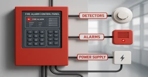
Specify an unshielded fire-resistant cable for general fire alarm and emergency communication circuits that are routed away from significant sources of electromagnetic interference, and where the panel manufacturer does not call for a shield.
Specify a shielded fire-resistant cable where circuits run near variable frequency drives, large motors, transformers, switchgear, elevator equipment or transmitting antennas, where an addressable loop has shown intermittent communication faults, or where the panel manufacturer requires it in the published installation instructions.
In both cases, the fire performance of the product is proved by its own fire test evidence, not by the presence or absence of a shield.
What a Shield Actually Does
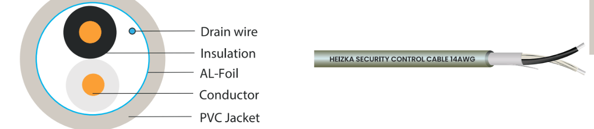
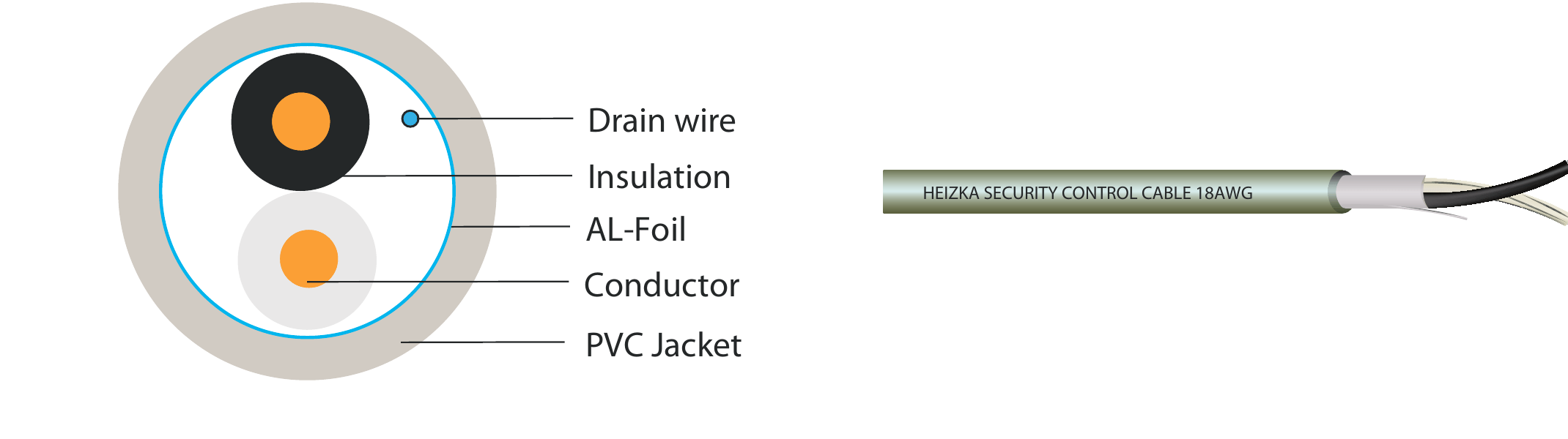
A shield is a conductive layer placed around the twisted pair or pairs, usually an aluminium or polyester foil, a tinned copper braid, or both together. It gives induced noise currents a low-impedance path to earth instead of allowing them to develop as a differential voltage across the signal pair.
The twisted pair is the first line of defence. Twisting causes noise induced in one conductor to be induced almost equally in the other, so the receiver sees very little difference between them. The shield handles what twisting alone cannot: capacitively coupled noise and higher-frequency energy radiated by nearby equipment.
A shield only works if it is terminated. An unterminated shield, or one broken at a junction box, is an antenna rather than a barrier and can make a circuit behave worse than it would with no shield at all.
Shielded vs Unshielded Fire-Resistant Cable: Construction Compared
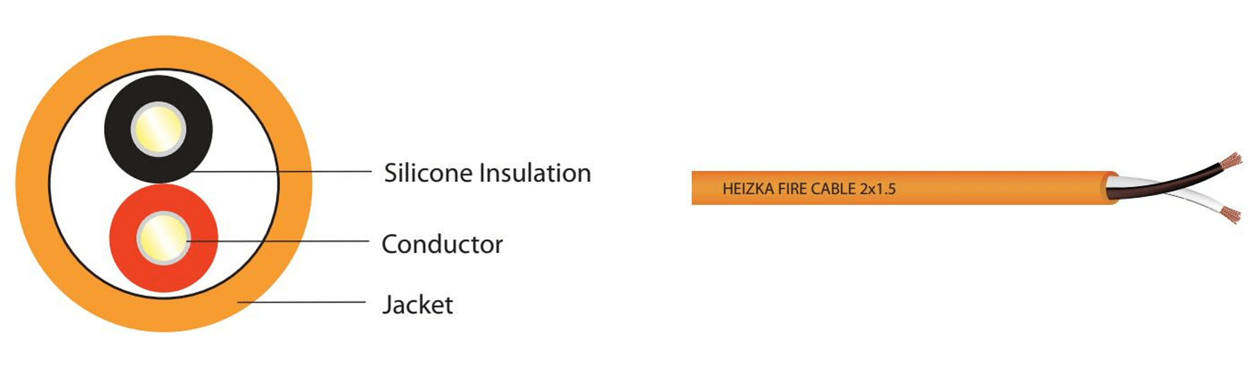
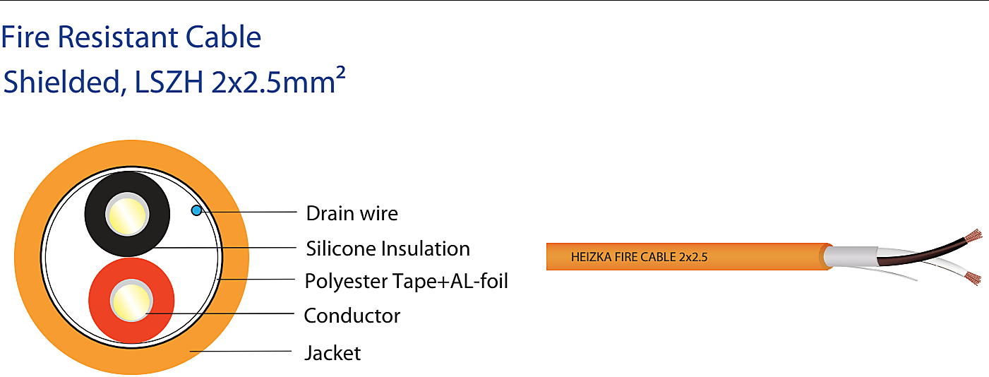
Both constructions normally start from the same core design: annealed copper conductors, a mica-glass tape or equivalent fire barrier that preserves insulation during a fire, insulated conductors twisted into pairs, and a jacket selected for the installation environment.
The shielded fire-resistant cable inserts a foil or braid layer, and usually a tinned copper drain wire, between the twisted pair and the jacket. Everything else about the fire-performance design is unchanged, which is why a shield cannot be treated as a fire-performance upgrade.
| Characteristic | Unshielded | Shielded |
|---|---|---|
| Noise rejection | Twisted pair only | Twisted pair plus conductive screen |
| Overall diameter | Smaller | Larger, affects conduit fill |
| Mutual capacitance | Lower | Higher, can limit loop length |
| Termination effort | Two conductors | Two conductors plus drain wire |
| Installed cost | Lower | Higher material and labour |
| Fire performance | Set by the fire test evidence | Set by the fire test evidence |
When to Specify a Shielded Fire-Resistant Cable
Shielding earns its cost when the route cannot be kept clear of noise sources. Typical triggers include:
- Routes that run parallel to power feeders, busway or switchgear, especially where the required separation cannot be maintained over a long distance.
- Plant rooms and risers containing variable frequency drives, soft starters, large motors, chillers or elevator controllers.
- Proximity to transmitting equipment such as two-way radio antennas, distributed antenna systems or paging amplifiers.
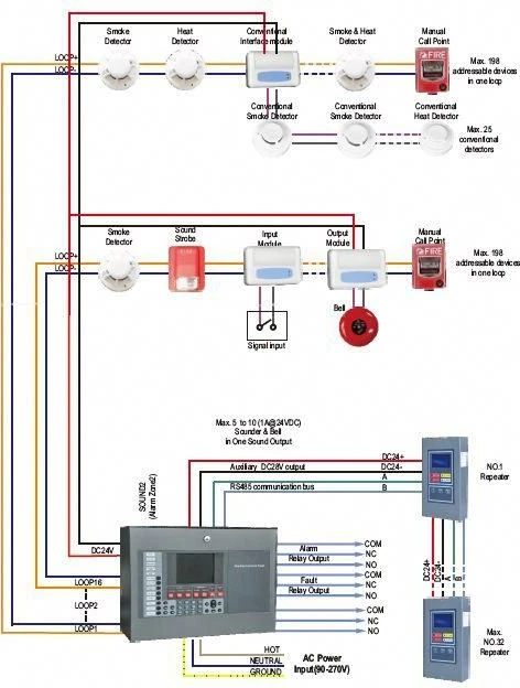
- Addressable signalling line circuits that have already shown intermittent device faults, checksum errors or communication dropouts.
- Industrial sites with welding equipment, induction heating or high-current rectifiers.
- Any case where the panel manufacturer specifies a screened cable in its published installation instructions.
The last point is the one most often overlooked. Fire alarm panels are listed as systems, and installing a cable that does not meet the manufacturer instructions can put the whole installation outside its listing.
When an Unshielded Fire-Resistant Cable Is Enough
An unshielded fire-resistant cable is appropriate, and usually preferable, for the majority of building circuits:
- Notification appliance circuits and initiating device circuits in offices, schools, hotels, retail and residential buildings.
- Routes that keep the required separation from power conductors along their whole length.
- Projects where the panel manufacturer permits an unshielded fire-resistant cable and the design has no unusual noise exposure.
- Long addressable loops where the lower capacitance of an unshielded fire-resistant cable helps keep the loop within the panel limit.
Choosing an unshielded fire-resistant cable here is not a compromise. It reduces diameter, simplifies termination, removes a whole class of grounding errors, and lowers cost without affecting fire performance.
Foil, Braid and Combination Shields
Foil shields
An aluminium-polyester foil gives full coverage around the pair and is effective against higher-frequency and capacitively coupled noise. It is light and low in cost, but it is thin, offers little mechanical protection, and must be terminated through the drain wire because the foil itself cannot be clamped reliably.
Braided shields
A tinned copper braid typically provides between 60 and 95 percent coverage. Its lower resistance gives better performance against lower-frequency interference and it survives repeated flexing and pulling far better than foil. It costs more, adds diameter, and takes longer to terminate neatly.
Combination shields
Foil plus braid gives broadband coverage and mechanical robustness together. It is the usual choice for severe electrical environments, at the cost of the largest diameter, the highest price and the most termination time.
Grounding the Shield Correctly
A screen only diverts noise if it has a defined path to earth. For the low-frequency interference that dominates in fire alarm wiring, the shield is normally bonded at one end only, at the control panel, so that no current can circulate through the screen between two separate earth references.
Bonding both ends creates a ground loop. Any difference in earth potential between the two locations drives current along the screen, and that current couples straight back into the pair it was supposed to protect. The symptom is usually intermittent, load-dependent faults that are very hard to trace.
The shield must also be continuous. At every junction box the drain wires are joined so the screen stays electrically whole from the first device to the panel, and the screen is insulated at the field end so it cannot touch enclosures, conduit or device terminals.
Two rules apply without exception: the screen is never used as a circuit conductor or as an equipment grounding conductor, and the panel manufacturer instructions take precedence when they specify something different from the general practice above.
Electrical Side Effects of Adding a Shield
A screen sits close to the conductors, so it raises the mutual capacitance of the pair. On addressable signalling line circuits the panel publishes a maximum capacitance per loop, and a shielded fire-resistant cable reaches that limit over a shorter distance than an unshielded fire-resistant cable of the same size. On long loops this can force a larger conductor, a shorter run or an extra loop card.
Diameter matters too. A shielded fire-resistant cable is larger, which affects conduit and tray fill calculations, bend radius and the practical pulling tension on long vertical risers.
Finally, termination time is real. Every device position needs the drain wire handled, joined and insulated. On a large system that is a measurable labour cost, and it is also the most common place for an installation error to appear.
Separation Comes Before Shielding
Physical separation is the cheapest and most reliable noise control measure available, and it should be exhausted before a shielded fire-resistant cable is added to the specification. A route that keeps a clear distance from power feeders, drives and switchgear will usually behave well with an unshielded fire-resistant cable, while a route pressed against a busway will misbehave even with a shielded fire-resistant cable.
Where a signal route has to meet a power route, crossing at right angles limits the length over which the two run in parallel and therefore limits the energy that couples across. Long parallel runs in a shared tray are the worst case and should be designed out at the drawing stage rather than corrected on site.
Keep the required segregation between power-limited fire alarm circuits and power conductors along the whole route, not just at the point where an inspector is likely to look. Where a shared containment route is unavoidable, a metallic barrier or a separate compartment in the tray restores much of the benefit and can avoid the need for a shielded fire-resistant cable altogether.
Commissioning Checks Worth Recording
- Continuity of the drain wire of a shielded fire-resistant cable from the last device back to the bonding point at the panel.
- Confirmation that the screen is isolated from enclosures, conduit and device terminals at the field end.
- Insulation resistance between conductors, and between each conductor and the screen.
- Loop resistance and measured capacitance against the panel published limits.
- A record of any deviation from the approved submittal, agreed in writing before energising the circuit.
Recording these values at handover gives the maintenance team a baseline. When a fault appears two years later, a measured comparison is far more useful than a discussion about what the installation should have looked like.
Standards and Codes to Reference
Fire performance
Circuit integrity is proved by test, and the specification should name the exact standard and category rather than a family. IEC 60331 covers circuit-integrity test methods for cables required to keep operating under fire conditions. BS 6387 uses category letters for flame exposure, flame with water spray and flame with mechanical shock. Flame propagation is a separate matter covered by the IEC 60332 series, and it is not interchangeable with circuit integrity, as explained in our guide to fire-resistant and flame-retardant cable differences.
Installation and system codes
In North America, NFPA 72 governs the installation, testing and maintenance of fire alarm and signalling systems and requires equipment to be installed in accordance with the manufacturer published instructions. The wiring methods, circuit classification and separation requirements for power-limited fire alarm circuits sit in Article 760 of NFPA 70, the National Electrical Code. Together they decide whether a screen is required, how the circuit is separated from power wiring, and how the whole system is inspected.
Product listings matter as well. In the United States, cables for power-limited fire alarm circuits are commonly listed to UL 1424, while UL 2196 covers the fire-resistive rating of a complete cable system as installed. Confirm that the listing on the data sheet of the shielded fire-resistant cable or unshielded fire-resistant cable you intend to supply is the listing the authority having jurisdiction expects to see.
Common Specification Mistakes
- Treating a screen as a fire-performance upgrade. It is an electromagnetic measure and changes nothing about circuit integrity.
- Bonding the screen at both ends. This creates a ground loop and typically produces intermittent, hard-to-reproduce faults.
- Breaking screen continuity at junction boxes. A drain wire left unconnected turns the screen into an antenna.
- Ignoring the capacitance limit. A shielded fire-resistant cable loop can exceed the panel limit well before the length limit is reached.
- Mixing constructions on one loop. Partial screening gives inconsistent behaviour and complicates fault finding.
- Substituting a shielded fire-resistant cable without new evidence. A different construction is a different product and needs its own fire test report.
- Specifying a screen instead of separation. Physical separation from power conductors is cheaper and more effective, and should always be the first mitigation.
Selection Checklist
- Read the panel manufacturer installation instructions first and record what they require.
- Walk the route on the drawings and list every noise source within the separation distance.
- Confirm the required fire-performance standard and category for the circuit function.
- Check the loop capacitance budget against the candidate product data sheet.
- Confirm conduit and tray fill with the actual overall diameter of the product.
- Agree the grounding detail, single-end bonding point and junction box treatment before installation starts.
- Keep the test report, data sheet and approved submittal together in one revision-controlled package.
Heizka Shielded and Unshielded Fire-Resistant Cable Options
Heizka supplies both constructions in matching sizes so a project can standardise on one family and switch construction only where the electromagnetic environment requires it.
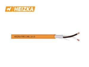
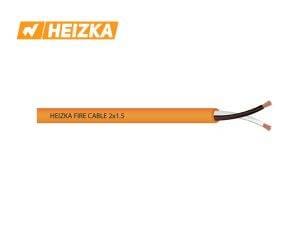
- Shielded, LSZH 2×1.5mm2 and shielded, LSZH 2×2.5mm2 for noisy plant rooms, risers and industrial routes.
- Unshielded, LSZH 2×1.5mm2 and unshielded, LSZH 2×2.5mm2 for general building circuits.
- The full Heizka fire-resistant cable range and our fire alarm and emergency communication cabling solutions.
If you are unsure which construction a circuit needs, send us the panel model, route description and required standard and our engineering team will review the specification with you.
Frequently Asked Questions
Does a screen improve fire performance?
No. Circuit integrity comes from the fire barrier and the overall construction, proved by a fire test. A screen is an electromagnetic measure only.
Can the screen be bonded at both ends?
Not as general practice. Single-end bonding at the panel avoids circulating current between two earth references. Follow the panel manufacturer instructions if they state otherwise.
Is a screened cable required by fire alarm codes?
Codes do not usually mandate one. The requirement normally comes from the panel manufacturer published instructions, which the installation code then obliges you to follow.
What braid coverage should be specified?
Typical braids run from about 60 to 95 percent coverage. Higher coverage improves low-frequency performance and increases cost, diameter and termination time.
Can shielded and unshielded fire-resistant cable be mixed on one loop?
Avoid it. Partial screening gives inconsistent noise behaviour and makes fault finding considerably harder.
Does a screen shorten the maximum loop length?
It can. Higher mutual capacitance means the panel capacitance limit is reached over a shorter distance, so check the loop budget before committing to a route.
Is LSZH related to screening?
No. Low smoke zero halogen describes the jacket compound and the smoke and acid gas it produces. It is independent of both screening and circuit integrity.
Match the Shielded or Unshielded Fire-Resistant Cable to the Route
Fire performance and noise immunity are separate requirements and should be specified separately. Decide the fire-performance standard and category from the function of the circuit, then decide the construction from the electromagnetic environment of the route and the panel manufacturer instructions.
Applied that way, the choice becomes straightforward: keep circuits away from noise sources wherever the layout allows, use an unshielded fire-resistant cable for ordinary building routes, and reserve the shielded fire-resistant cable for the places that genuinely need it.
References and Source Notes
- IEC 60331-1:2018, circuit-integrity test methods for cables under fire conditions
- IEC 60331-3:2018, circuit-integrity test procedure for cables tested in a metal enclosure
- BSI, BS 6387, test method for resistance to fire of cables required to maintain circuit integrity
- NFPA 72, National Fire Alarm and Signaling Code
Standards are cited for identification only. Always confirm the current edition and the exact category or part number applicable to your project, and verify that any test report you rely on covers the specific product, size and manufacturing site being supplied.
Technical Review by John Smith
Cable Product Engineer
12 Years in Structured Cabling & Low Voltage Systems