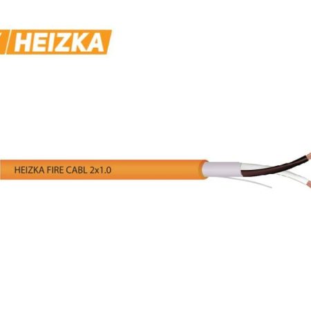
Fire-Resistant Cable 2×1.0 mm²
The 2×1.0 mm² size is the smallest conductor in the Heizka Fire Cable range and the one most often pulled for detection and low-current signaling circuits. Both variants use stranded bare copper on a 16/0.24 mm construction, silicone insulation at 100% coverage and an orange LSZH jacket, rated 300 V with 2000 V dielectric strength. Published maximum DC resistance is 21.4 Ω/km at 20 °C, the highest in the range, which is why size selection here is a volt-drop calculation rather than a preference.
Products in This Size
| Product | Screen | Jacket thickness / OD | Published capacitance |
|---|---|---|---|
| Fire Resistant Cable Shielded, LSZH 2×1.0 mm² | Polyester tape + aluminum foil, 100% coverage, drain wire 7/0.18 TC mm | 0.7 ± 0.1 mm / 5.7 ± 0.3 mm | 98 ± 3 pF/m |
| Fire Resistant Cable Unshielded, LSZH 2×1.0 mm² | None | 0.7 ± 0.1 mm / 5.6 ± 0.3 mm | Not published |
Both are supplied at 500 m per reel with sequential footage markers and cite IEC 60331-1, IEC 60332-1, EN 50200, EN 61034-2, BS 5839-1, BS 6387 and CNS 11175, plus ISO 9001 and RoHS compliance. The listings cite BS 6387 and EN 50200 without category letters or a PH class, so confirm the applicable category, standard part and edition against the current test report for this part number before submittal.
Volt Drop Is the Governing Constraint at 1.0 mm²
At 21.4 Ω/km per conductor, a two-core circuit presents roughly 42.8 Ω/km of loop resistance, or about 4.28 Ω per 100 m of route, derived from the published DC resistance at 20 °C and to be corrected upward for elevated ambient conditions and termination resistance. For a detector loop drawing tens of milliamps, that is immaterial. For a circuit holding a relay or driving a sounder, it becomes the limiting factor long before any thermal rating does, and the answer is to step up to 2×1.5 mm² or 2×2.5 mm² rather than extend the run. No ampacity table is published for this range, so confirm current-carrying capacity and grouping or ambient derating against the datasheet and installation method.
Typical Circuits and Installation Practice
This size suits addressable and conventional detector loops, initiating device circuits, interface modules and supervisory signaling where current draw is low and device count per run is high. The advantages are physical: at 5.6 to 5.7 mm outside diameter this is the smallest cable in the range, so it consumes the least conduit and tray fill, tolerates the tightest bend radius, and leaves the most room in a crowded backbox. Termination is the trade-off. A 16/0.24 mm stranded conductor is flexible and should enter cage-clamp and screw terminals with a ferrule so strands are not spread or severed under the clamp. Where a compression gland is used, verify it accepts a 5.6 to 5.7 mm jacket.
Shielded or Unshielded at This Size
The screen is an electromagnetic compatibility choice, not a fire-performance one. It matters most at 1.0 mm² because this is the size used on long addressable loops, and the shielded variant’s 98 ± 3 pF/m mutual capacitance accumulates over distance. Check total loop capacitance against the panel manufacturer’s published maximum before committing to shielded construction on a long run; unshielded is often the better electrical answer where separation from power cabling can be maintained. If shielded, bond the screen at the control panel end only, keep the drain wire continuous, isolate it at the field end, and never mix shielded and unshielded cable on one loop. See shielded versus unshielded fire-resistant cable, fire-resistant versus flame-retardant cable and the cabling solutions overview.
Frequently Asked Questions
How many devices can I put on one 2×1.0 mm² run?
That is set by the panel, not the cable. Total the quiescent and alarm current of every device, apply it across the loop resistance for your route length, and confirm the voltage at the furthest device meets the panel’s minimum. Loop capacitance is a second, independent limit on addressable circuits.
Is 1.0 mm² acceptable for sounder or notification circuits?
Only if the volt-drop calculation supports it. Notification circuits draw far more current than detection circuits, and at 4.28 Ω per 100 m the voltage at the last device falls quickly. Most sounder circuits of any length move to a larger cross-section.
Does the silicone insulation replace a mica tape barrier?
The published construction lists silicone insulation at 100% coverage; no mica tape layer is stated on the product page. If your specification calls out a mica-glass barrier, confirm the construction against the current datasheet and test report before submitting it.
To price this size, confirm shielded or unshielded construction, or request test documentation for a tender, send the part number, quantity and destination through contact us. Stating the fire-performance category and panel manufacturer up front lets the team confirm the correct variant on the first reply.