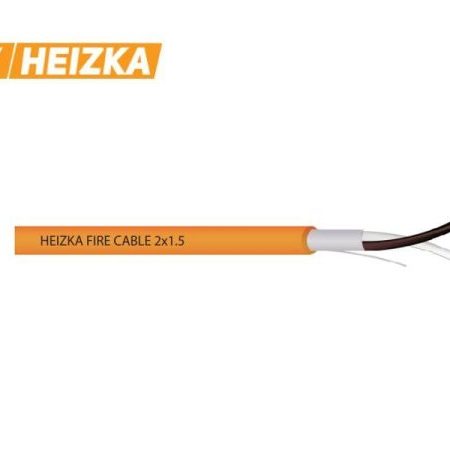
Fire-Resistant Cable 2×1.5 mm²
The 2×1.5 mm² size sits in the middle of the Heizka Fire Cable range and what most projects settle on once notification circuits are calculated. Both variants use stranded bare copper on a 30/0.24 mm construction, silicone insulation at 100% coverage and an orange LSZH jacket, rated 300 V with 2000 V dielectric strength. Published maximum DC resistance is 12.33 Ω/km at 20 °C, roughly 42% lower than the 1.0 mm² size for an outside diameter that grows by about one millimeter.
Products in This Size
| Product | Screen | Insulation thickness / diameter | Jacket thickness / OD |
|---|---|---|---|
| Fire Resistant Cable Shielded, LSZH 2×1.5 mm² | Polyester tape + aluminum foil, 100% coverage, drain wire 7/0.18 TC mm | 0.5 ± 0.05 mm / 2.5 ± 0.10 mm | 0.8 ± 0.1 mm / 6.7 ± 0.3 mm |
| Fire Resistant Cable Unshielded, LSZH 2×1.5 mm² | None | 0.5 ± 0.05 mm / 2.5 ± 0.10 mm | 0.8 ± 0.1 mm / 6.6 ± 0.3 mm |
Both are supplied at 500 m per reel with footage markers and cite IEC 60331-1, IEC 60332-1, EN 50200, EN 61034-2, BS 5839-1, BS 6387 and CNS 11175, plus ISO 9001 and RoHS. Published operating temperature ranges differ between the two listings, so read that figure from the datasheet for the exact part number. BS 6387 and EN 50200 are cited without category letters or a PH class; confirm the category, part and edition against the current test report before submittal.
Why 1.5 mm² Is the Common Notification-Circuit Size
At 12.33 Ω/km per conductor, a two-core circuit presents about 24.66 Ω/km of loop resistance, or roughly 2.47 Ω per 100 m of route, calculated from the published DC resistance at 20 °C. Compare about 4.28 Ω per 100 m at 2×1.0 mm². On a detector loop the difference is academic. On a sounder, strobe or voice-evacuation circuit, where alarm current is measured in amps rather than milliamps, that reduction decides whether the last device sits inside its minimum operating voltage. Size on end-of-line voltage under full alarm load, not nominal current, and correct the 20 °C resistance upward for real ambient conditions. No ampacity table is published for this range, so confirm current-carrying capacity and grouping derating against the datasheet.
Routing, Glanding and Termination
At 6.6 to 6.7 mm outside diameter this size still routes easily, but the increase over 1.0 mm² is enough to change conduit and tray fill on dense risers, and gland sizes should be checked rather than carried over. The 30/0.24 mm conductor holds its form better in a terminal than the smaller size, though ferrules remain good practice in cage clamps. Where circuits transition between sizes, document the junction, keep it out of a fire-rated boundary where the design allows, and record it in the as-built package. Fire test evidence applies to a tested construction, so a change of cross-section mid-circuit is a specification decision.
Shield Selection and Grounding
Both constructions carry the same fire-performance intent. The screen is an EMC measure, chosen on the electromagnetic environment: routes parallel to power feeders or busways, plant rooms with variable frequency drives or chillers, or a panel manufacturer that mandates screened cable. Where separation from power conductors can be maintained, unshielded is usually sufficient and avoids the added mutual capacitance. If shielded, bond the screen at the control panel end only, keep the drain wire continuous back to the bonding point, isolate it at the field end, and never use it as an equipment grounding conductor. See shielded versus unshielded fire-resistant cable.
Frequently Asked Questions
Does 1.5 mm² carry a different fire rating than 1.0 mm² or 2.5 mm²?
Fire test evidence is tied to the tested construction and cannot be assumed across sizes, even within one range. Request the test documentation covering the exact part number you intend to install.
What is the difference between IEC 60331 and IEC 60332 on this datasheet?
IEC 60331 tests circuit integrity, meaning whether the circuit keeps operating during a defined fire exposure. IEC 60332 tests flame propagation along the cable. They are separate properties, and evidence for one does not prove the other. Our article on fire-resistant versus flame-retardant cable explains the distinction.
Can I use this size for an emergency power run instead of a signaling circuit?
Check the volt drop first. Sustained load over a long route usually pushes the design to 2×2.5 mm². Also confirm the 300 V rating and published temperature range suit the circuit.
Where can I download the datasheet?
Catalogs, datasheets and certificates are available from Project Documents, no registration required.
For pricing, reel configuration or a submittal document pack on this size, send the part number, quantity and destination through contact us. Naming the governing standard, category and panel manufacturer in your first message lets the team confirm shielded or unshielded construction and supply matching test documentation without a second round of questions.