Overview
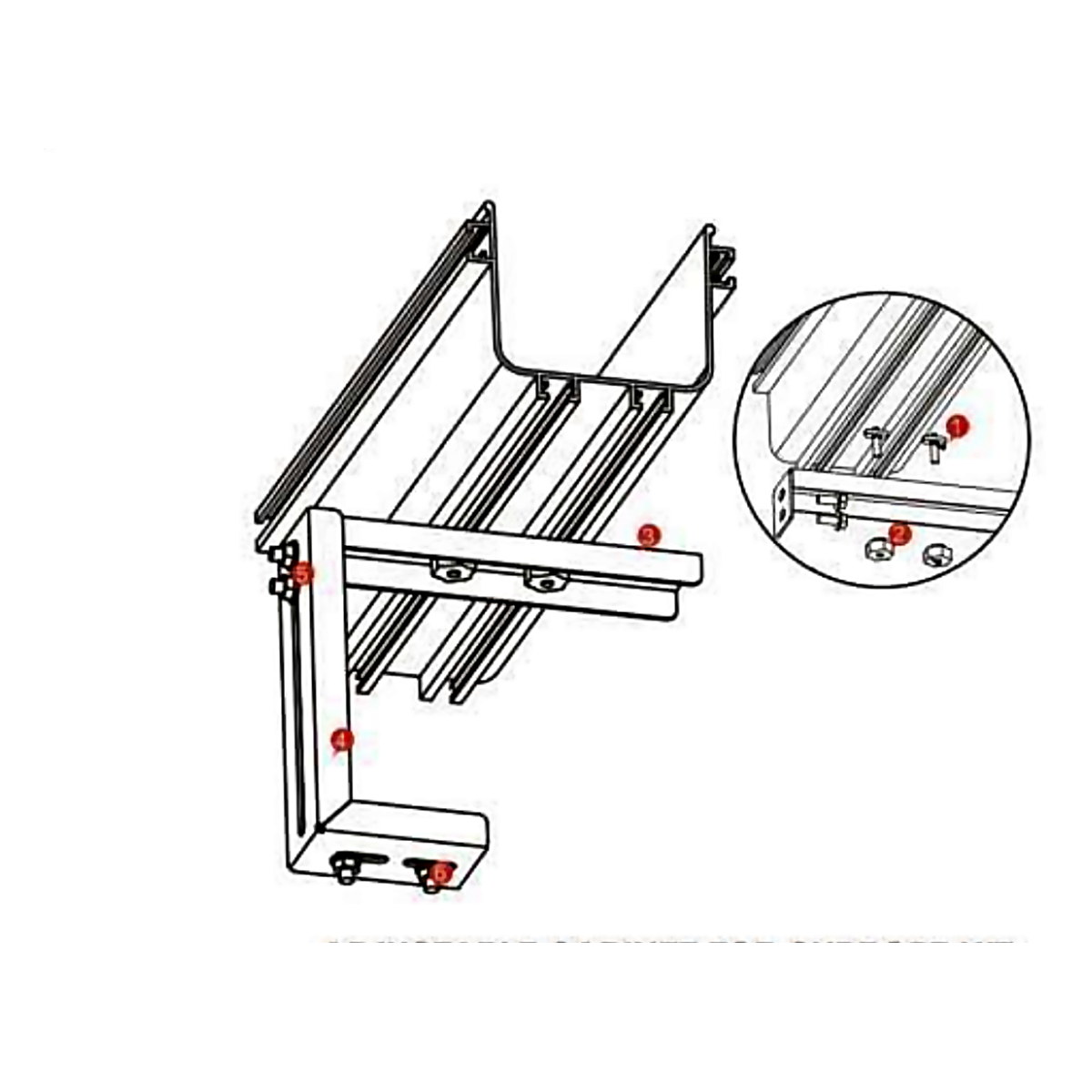
The Heizka Adjustable Cabinet Top Support carries the fibre raceway directly above a row of equipment cabinets or racks. The stand is height-adjustable from 50 to 200 mm, so the pathway can be set at a consistent height above cabinets of differing sizes.
The support bar bolts to the stand and the raceway clamps to the bar with plastic T-shape bolts and twist nuts, giving a clean, repeatable installation along the top of a cabinet row.
Key Features
- Height adjustable over a 50–200 mm range.
- Support bars sized for the 120 mm and 240 mm raceway series; the stand suits all sizes.
- Mounts the raceway on top of equipment cabinets, racks and frames.
- Electroplated zinc with powder-coated finish.
- Assembles with plastic T-shape bolts and twist nuts – no drilling of the raceway required.
Technical Specifications
Adjustable Cabinet Top Support Bar
| Item No. | L (mm) | Overall (mm) | Application range | Surface treatment |
|---|---|---|---|---|
| LI2G1 | 230 | 230 × 50 × 50 | 120 straight section | Electroplated zinc, powder coated |
| LI2G2 | 350 | 350 × 50 × 50 | 240 straight section | Electroplated zinc, powder coated |
Suits raceway sizes up to 240 mm; mounts with item no. LST30.
Adjustable Cabinet Top Support Stand
| Item No. | H (mm) | Overall (mm) | Application range | Surface treatment |
|---|---|---|---|---|
| LST30 | 200 | 100 × 50 × 200 | 50–200 | Electroplated zinc, powder coated |
Suits fibre raceway installation at cabinet top, mounting with the adjustable cabinet top support bar.
Cabinet top support kit contents
- LT147 Plastic T-shape bolt × 2
- LT343 Plastic twist nut × 2
- Adjustable cabinet top support bar × 1 (or dual-hole bar × 1)
- LST30 Adjustable cabinet top support stand × 1 (kit on catalogue page 58 shows × 2)
- M8 flange nut × 6
- M8 bolt × 6
Installation notes
- The cabinet top support kit shown on catalogue page 58 lists the adjustable cabinet top support stand × 2; the installation page on 59 lists × 1. Please confirm the quantity for your configuration with Heizka.
Dimensions are quoted from the Heizka Fibre Management System catalogue. Specifications are subject to change without notice – please confirm critical dimensions with Heizka before ordering.
Standards & Compliance
- Flame retardancy: UL94-V0 self-extinguishing plastics.
- Material: PVC / ABS mouldings; steel support hardware is electroplated zinc with a powder-coated finish.
- All plastic-based components are specified to be RoHS compliant.
- Colour: high-visibility yellow, identifying the fibre pathway.
- Environment: indoor use in data centres, telecommunication exchanges and equipment rooms.
When to Run the Raceway on Top of the Cabinets
A fibre route can hang from the ceiling, sit on a ladder rack, or rest directly on the cabinet row. The cabinet-top method is the shortest path between cabinets in the same row and needs no ceiling fixings, which helps where the slab above is congested with ducts, sprinkler pipes or power tray. It is also the easiest method to install in a live room, because no drilling above running equipment is needed.
Matching the Bar to the Raceway
| Part | Size (mm) | Raceway | Raceway overall width | Spare width on bar (calculated) |
|---|---|---|---|---|
| LI2G1 bar | 230 × 50 × 50 | 120 series | 158 mm | 72 mm |
| LI2G2 bar | 350 × 50 × 50 | 240 series | 278 mm | 72 mm |
| LST30 stand | 100 × 50 × 200 | All sizes | — | Height 50–200 mm |
Overall raceway widths are the published straight-section figures including flange and cover. The spare width on each bar leaves room for the clamping hardware on both sides of the channel.
Setting the Height
The stand adjusts over 150 mm (200 − 50, calculated). Use this range to level the route across cabinets of different heights, so the raceway runs straight instead of stepping up and down at every cabinet. When checking clearance to the ceiling, add the stand height, the support bar and the raceway’s overall height (118 mm for the 120 and 240 series) to the tallest cabinet in the row.
Planning Checklist
- Confirm the cabinet roofs can carry the stands and that the stand fixings do not block cable entry holes or fan trays.
- Decide the support spacing with the route designer and count one stand and one bar per support point.
- Where the route leaves the row, change to the ceiling or ladder-rack mounting kits.
- Plan drops into each cabinet with a trumpet spillout or movable exit so the 30 mm bend radius is kept.
Frequently Asked Questions
Can I use the cabinet top support for the 360 or 600 series?
The published support bars cover the 120 and 240 series; the stand suits all sizes. For other widths, ask Heizka to confirm the bar before ordering.
See the full Fiber Raceway System.
Typical Applications
- Data centres and server rooms – fibre patch cord routing between racks and rows.
- Telecommunication exchanges and central offices.
- Optical distribution frames (ODF) and fibre cross-connect areas.
- Any installation where fibre must be segregated from copper services and protected end to end.
Download
Catalogue extract for this product, taken from the Heizka Fibre Management System catalogue:
Heizka Cable — Designed in the USA, distributed in 20+ countries worldwide.